No sections found on this page yet.
What is kinematics?
Describing motion without asking why
Every one of those is a kinematics problem.
Kinematics asks: "What motion is happening?"
Dynamics asks: "What forces are causing it?"
We're only asking the first question today. Kinematics shows up everywhere: robot arms, video game animation, drones, self-driving cars, even the characters in your favorite game.

Coordinate frames
Where is 'here', exactly?
A location only makes sense once we pick a starting point and a set of directions. Together, that's called a coordinate frame: an origin (a "zero point") plus axes pointing in specific directions.
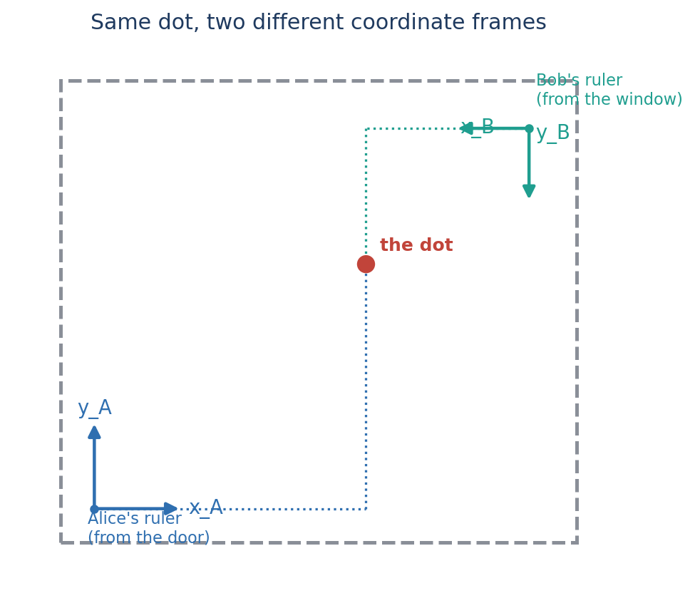
Sliding a frame: translation
Moving without turning
If both rulers point the same direction (nobody rotated anything), converting is just addition — like adding two trips end-to-end:
Sliding a frame: translation
Drag the teal frame B around. Click anywhere
to place (or move) the point, or drag it directly once it exists. Watch how ᴬp always equals ᴬd_B + ᴮp.
Click anywhere on the grid to place a point.
Turning a frame: rotation matrices
Describing a spin with numbers
In 2D, spinning counterclockwise by angle uses:
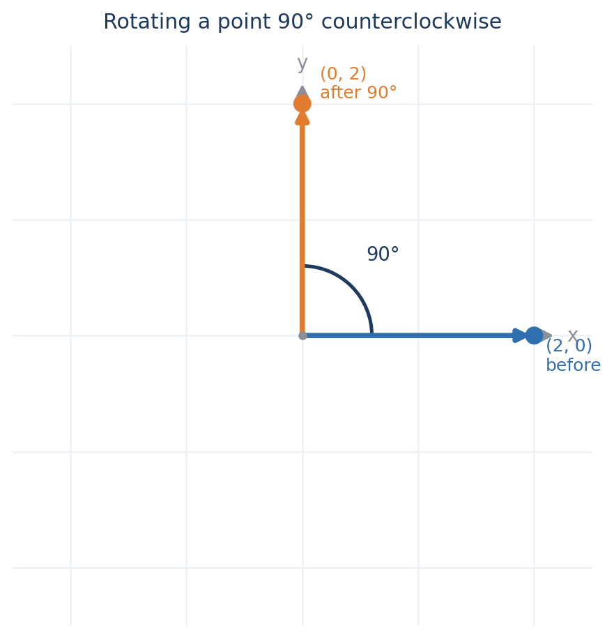
So where do and actually come from? Let's build the matrix from scratch instead of just memorizing it.
Start with the plain definition of sine and cosine you already know: on a circle of radius 1, if you sweep counterclockwise from the positive -axis by an angle , you land at the point
Now think about Frame . Before we rotate anything, its -axis points along — a unit-length arrow sitting at angle on that same circle. Once we spin Frame by , that arrow is still unit-length, just now sitting at angle :
What about Frame 's -axis? It's always exactly counterclockwise from its own -axis — that never changes, no matter how much we spin. Here's a handy geometric shortcut: rotating any vector by counterclockwise gives — just swap the two numbers and flip the sign of the new first one. Apply that shortcut to :
Now for the payoff. A point written in Frame 's coordinates, , is really just an instruction: "walk steps along , then steps along ." Since we now know exactly where those two axes point using Frame 's ruler, we can just add the trip up:
So a rotation matrix's columns are literally the unit axes of Frame , written using Frame 's ruler. And because those axes always stay perpendicular and unit-length, flipping the matrix (its transpose ) exactly reverses the spin.
A rotation matrix isn't just a grid of magic numbers — its columns are literally the unit axes of Frame written down using the coordinate ruler of Frame . The first column tells you where Frame 's -axis points, and the second column tells you where its -axis points.Because these axes remain perpendicular and unit-length no matter how much you turn them, flipping the matrix upside down (taking its transpose ) perfectly reverses the rotation.
Turning a frame: rotation
Drag the teal handle to spin frame B around the
shared origin. Click anywhere to place a point (it stays physically fixed).
Watch how ᴬp = R(θ) ᴮp, and how the dotted lines show
cos θ and sin θ as B's axes swing across A's axes.
Click anywhere on the grid to place a point.
Rotating in 3D
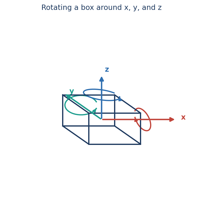
Spinning around x, y, or z
Wait — why is 's pattern backwards? Look closely: in and , the minus sign sits in the upper-right corner of the little 2×2 block and the plain sits in the lower-left. In , it's flipped: is upper-right and is lower-left. That's not a typo — it happens for a real geometric reason.
Here's the key idea: rotating around one axis always mixes the other two. Which one turns into which is set by the right-hand rule — point your right thumb along the positive axis you're spinning around, and your fingers curl in the direction of positive rotation. That last one is the whole story. The three axes take turns in a repeating cycle:
Now here's the catch: no matter which axis we spin around, we always write the matrix using the same fixed left-to-right, top-to-bottom order: . For and , the pair being mixed already comes in that natural order ( then ; then ), so the familiar pattern drops in unchanged. But for , the pair being mixed is really , and we're forced to write it in the "wrong" order, , to match everyone else's layout. Writing a rotation block with its two axes swapped is exactly the same as taking its transpose — and transposing a 2D rotation block flips the sign of both entries.
You can see it directly. If 's rotation followed the same naive pattern as the other two, it would incorrectly look like:
Chain them together to build any orientation you want:
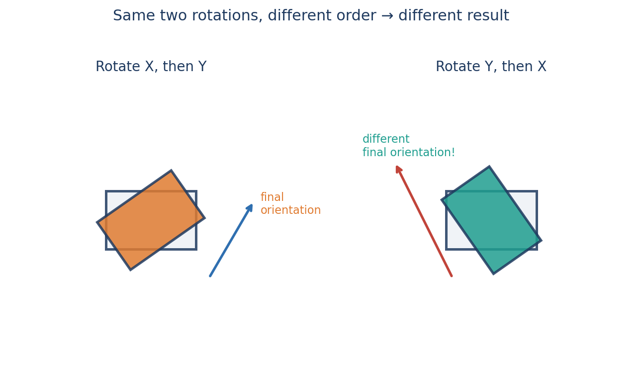
Order matters!
Why 3D rotations aren't like ordinary addition
Roll, pitch, yaw & gimbal lock
Two ways to stack up rotations
With fixed-axis rotations, every spin happens around the room's axes, which never move.
With Euler-angle rotations, each spin happens around the object's own axes, which move along with it after every turn.
Airplanes make this intuitive:
- Roll: tipping side to side
- Pitch: nose up or down
- Yaw: turning left or right
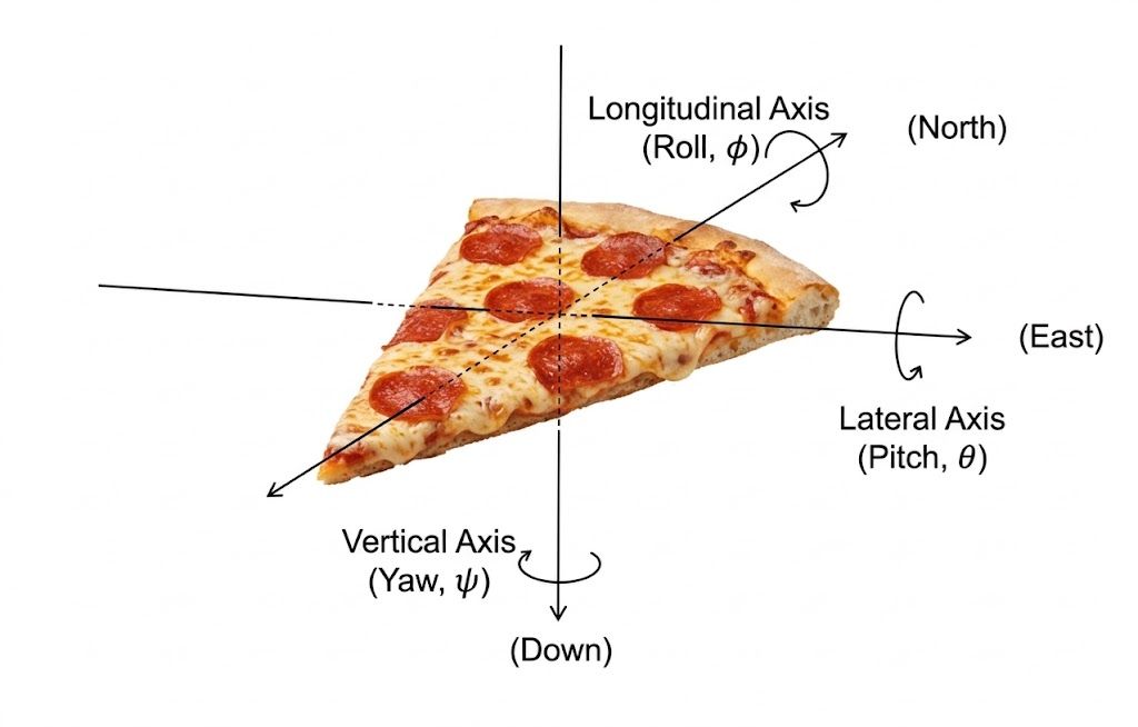
These angles are easy to picture, but they have a famous flaw called gimbal lock: at certain orientations, two of the three rotation axes line up on top of each other, and you suddenly lose the ability to turn one whole direction — even though the object itself is perfectly fine.
Degrees of freedom & configuration space
How many numbers does it take to describe a system?
A checker piece sliding around on a flat table needs two numbers: A drone flying freely through the air needs three, plus three more for which way it's facing — six total.
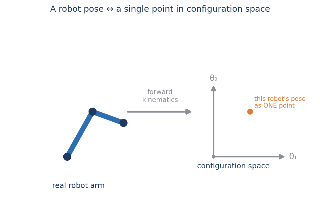
Robot manipulators build up motion using two primary joint types:
- Revolute joints: spin around an axis (like an elbow or shoulder)
- Prismatic joints: slide linearly along an axis (like a telescope arm, elevator, or 3D printer axis)
Each joint contributes one degree of freedom to the system's configuration space, whether it measures an angle or a sliding distance .
Q1. A bead slides along a single curved wire. How many degrees of freedom does it have?
Homogeneous coordinates
Turning and sliding in one single step
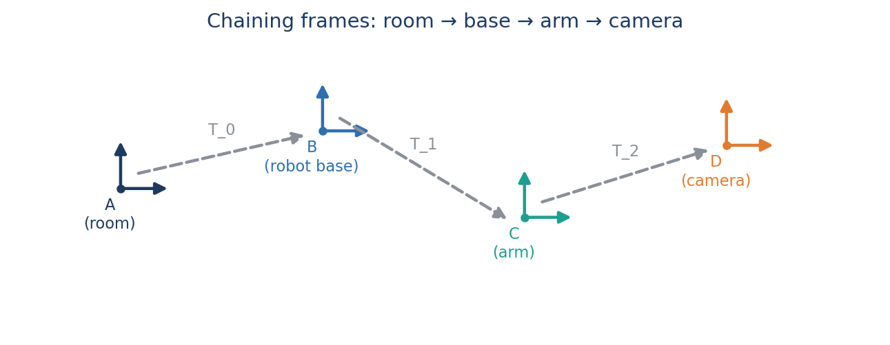
Chaining coordinate frames
Connecting many small moves into one big one
Forward kinematics
From joint variables to hand position
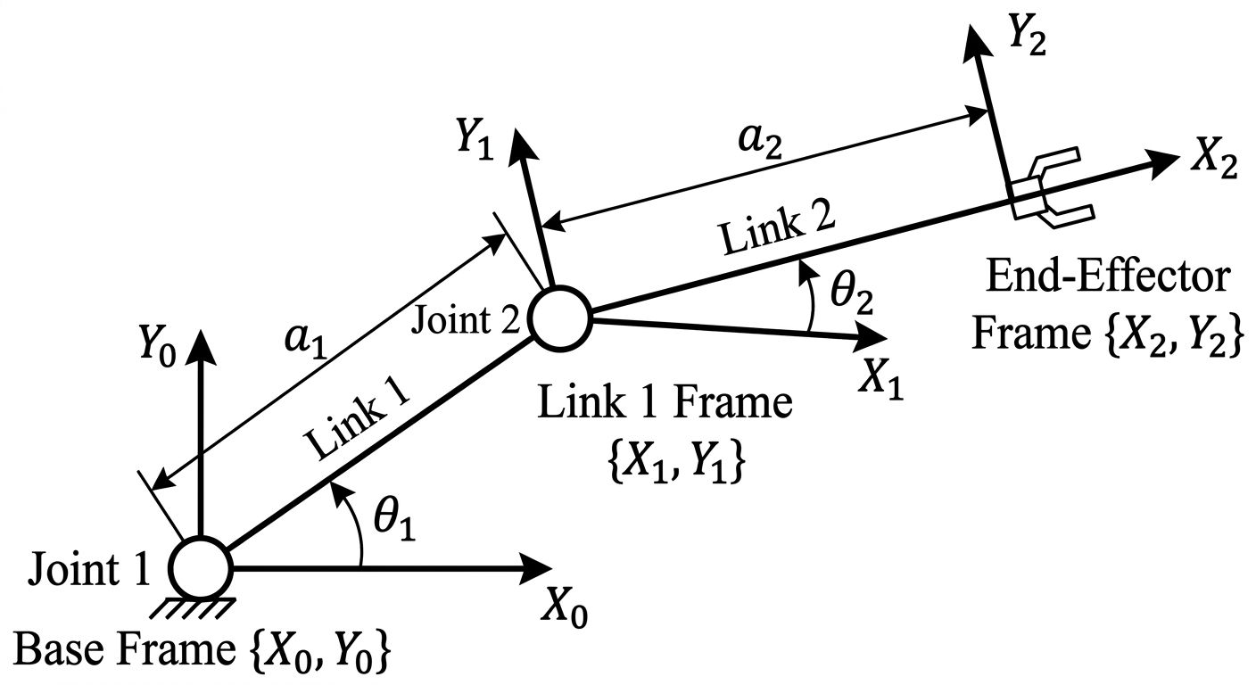
For our two-link arm, we can think of each joint as creating a new coordinate frame. Frame 0 is attached to the robot's base, frame 1 is attached to the elbow, and frame 2 is attached to the hand. Each transformation tells us how to move from one frame to the next.
For example, the transformation from the base to the elbow consists of a rotation by followed by a translation of along the new link:
We can then multiply the two transformations together:
Notice what happened: instead of deriving the position of the hand directly with trigonometry, we built the robot one joint at a time. The first transformation takes us from the base to the elbow; the second takes us from the elbow to the hand. Multiplying them creates the complete transformation from the base to the hand.
This is the power of a chain of frames. For a two-link arm, the chain is short:
So far every joint has been revolute — it spins, but the link attached to it never changes length. Real robots also use prismatic joints, which don't rotate at all. They just slide in and out, like a drawer or a car antenna.
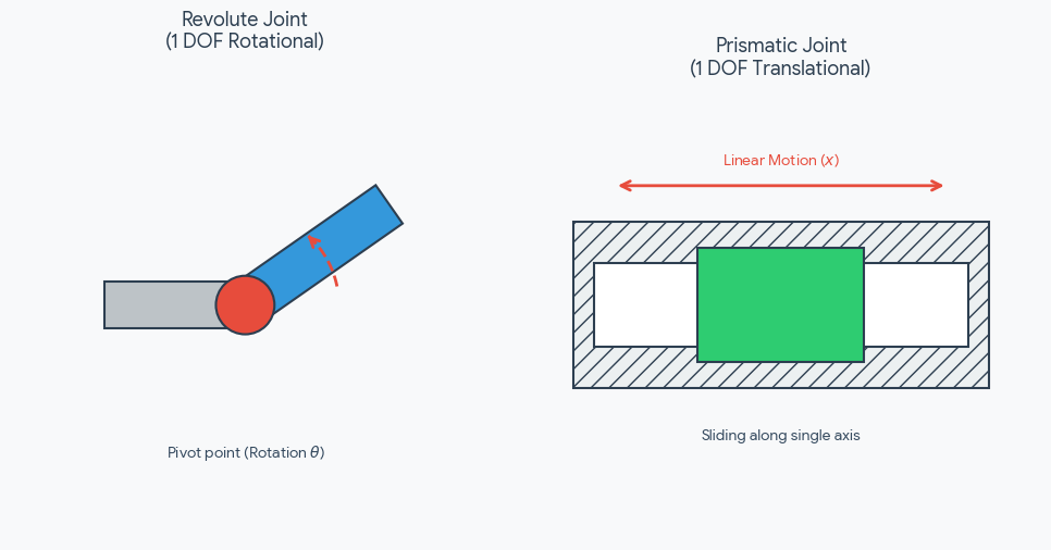
Worked example — a revolute-then-prismatic ("R-P") arm: Suppose joint 1 is revolute (it aims the arm at angle ) and joint 2 is prismatic (it telescopes outward by a variable distance , sliding along the direction joint 1 already set). Multiplying the two blocks above:
Inverse kinematics
From where you want your hand to what angles to use
Suppose we have a simple robotic arm with two rigid links. The first link has length , the second has length , and the hand needs to reach the target point . The inverse-kinematics problem is: what joint angles will put the hand there?
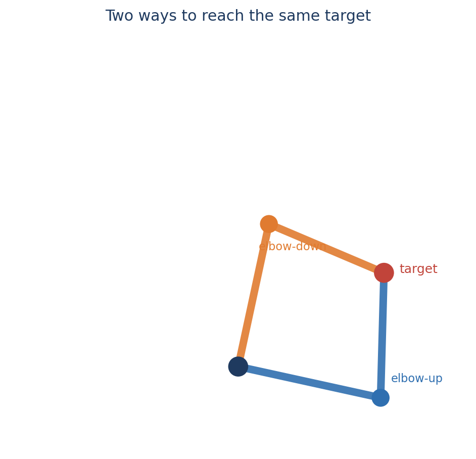
This is harder than forward kinematics because there may be multiple answers. The arm might reach the same point with its elbow up or elbow down. Some points can be reached in only one way, while points outside the arm's reach cannot be reached at all.
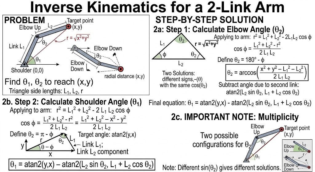
Step 1 — Find the elbow angle.
Imagine drawing a line from the shoulder joint directly to the target. Its length is
Now we can use the law of cosines. For any triangle with side lengths and angle opposite side ,
In our robot arm, the side opposite the elbow angle is , while the other two sides are and . Therefore,
Solving for the cosine gives
and substituting gives
The joint angle is often defined as the angle between the two links when they are folded in the robot's usual joint-coordinate convention. With that convention, , so . Therefore,
This is where the law of cosines leads directly to the inverse-kinematics equation: the desired position determines the third side of the triangle, and the three side lengths determine the elbow angle.
Why are there two solutions?
The same three side lengths can form a triangle in two mirror-image ways. The elbow can bend above or below the line from the shoulder to the target. These are the elbow-up and elbow-down configurations. They correspond to opposite signs for , even though they have the same value of .
Step 2 — Find the shoulder angle.
First, tells us the angle from the positive x-axis to the line connecting the shoulder to the target. We then subtract the angle contributed by the second link:
The second comes from the same triangle geometry. The second link contributes a vertical component and, together with the first link, a horizontal component . Thus, its angle is
and subtracting this from the target direction gives the shoulder angle.
What if the target cannot be reached?
The law of cosines also tells us when a solution exists. For the inverse cosine to produce a real angle, its argument must lie between and . Geometrically, this is exactly the requirement that the three lengths can actually form a triangle.
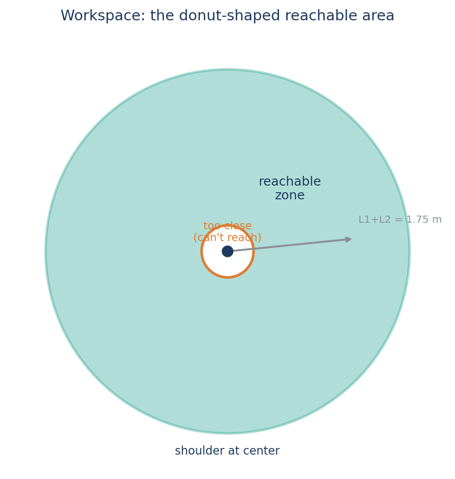
For a two-link arm, the hand can reach points satisfying
The outer limit is the arm fully extended. The inner limit occurs when the links are folded as tightly as possible. A target outside this region has no inverse-kinematics solution.
Workspace
Where can the robot's hand actually go?
For a two-link arm:
Workspace
Drag the elbow to change θ₁, drag the hand to change θ₂, or use the sliders.
The shaded donut is every point the hand can possibly reach. Click anywhere to
drop a test point and see if it falls inside.
Click anywhere to test whether that point is reachable.
Configuration space vs. task space
The robot's inner world vs. the outer world
Here's the twist: elbow-up and elbow-down are two completely different configurations, but they can put the hand at the exact same task-space point.
The Jacobian
Turning joint speed into hand speed
The answer is the Jacobian matrix — a table of "how much does each output change when I wiggle each input a tiny bit":
Singularities
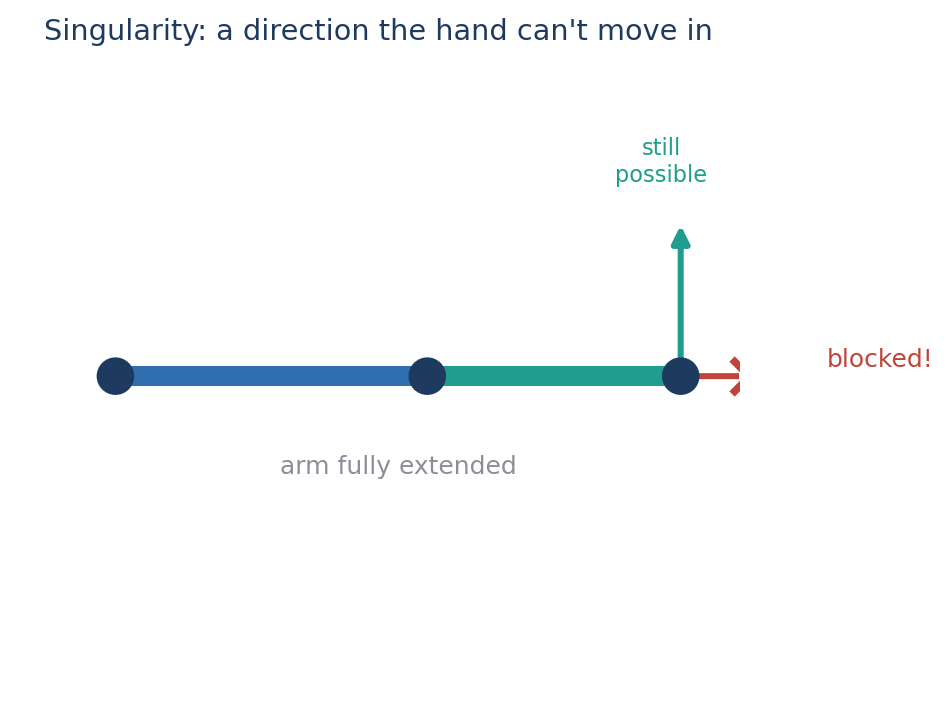
When a robot loses a direction of motion
This is a kinematic singularity: a pose where the Jacobian loses the ability to move the hand in some direction. Mathematically, this happens when:
Other ways to describe orientation
Quaternions and screw motion
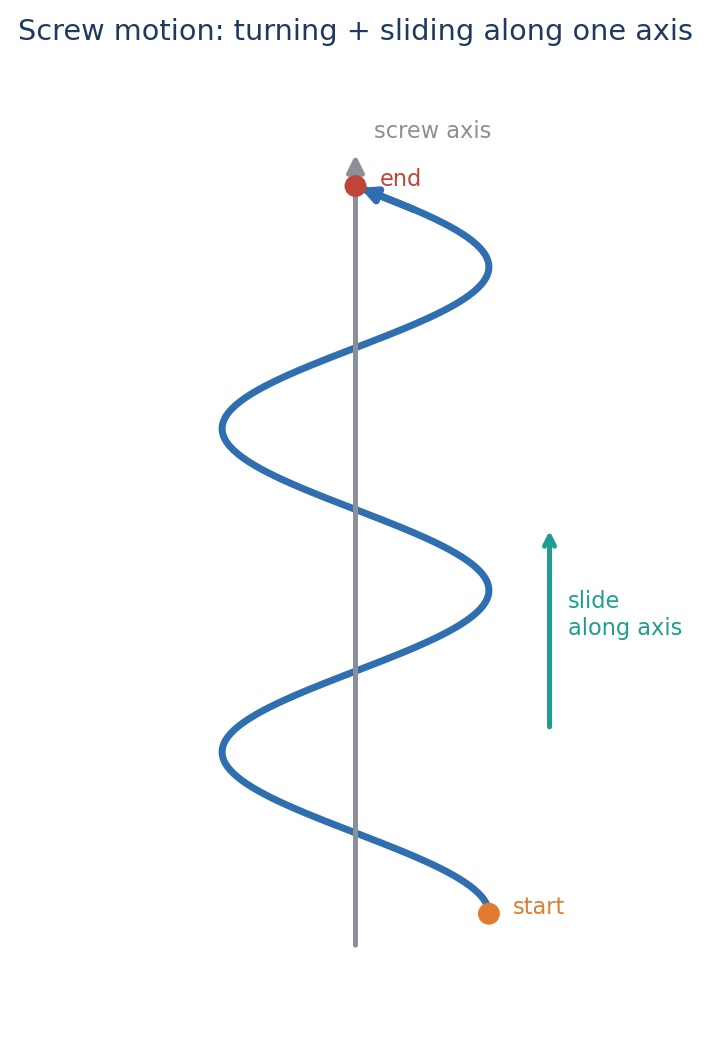
There's an even deeper idea called screw motion: any rigid movement — no matter how complicated — can be described as a rotation around an axis plus a slide along that same axis, just like turning a screw into wood.
Putting it all together
The big picture
Capstone challenge: retrieve the sample
Put everything together on a Mars rover
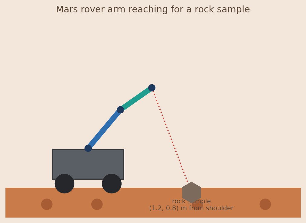
2. Find θ₂. Use the law-of-cosines formula. Why might there be two valid answers?
3. Find θ₁. Use the formula.
4. Check your work. Plug your angles back into the forward-kinematics equations. Do you land near ?
5. Configuration space check. Sketch elbow-up and elbow-down. How can two different configurations give the same hand position?
6. Add an obstacle. A rock blocks the elbow-up pose. Does the inverse-kinematics math still work? Is it still a usable robot motion?

Exit questions
2. Why does the order of 3D rotations matter?
3. What's the difference between configuration space and the physical space around you?
4. Why are homogeneous coordinates useful?
5. What's the difference between forward and inverse kinematics?
6. Why can inverse kinematics have more than one answer?
7. In plain English, what does the Jacobian tell us?
8. What happens to a robot near a singularity?
9. Why might an engineer choose a quaternion over Euler angles?
10. What's the one big idea that connects coordinate frames, forward kinematics, inverse kinematics, and the Jacobian?